Back
THOR: Wireless Circuitboard Design (V2)
Project Overview: Wireless-enabled PCB design for controlling three stepper motors, featuring RF communication, autonomous operation capabilities, and integrated power management.
PCB Layout
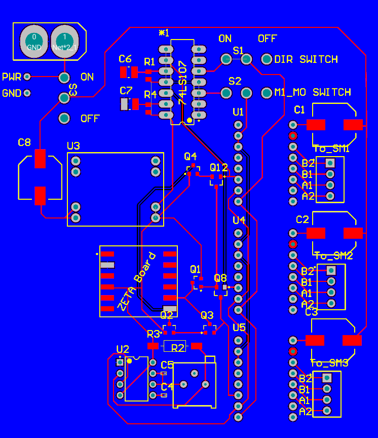
2D PCB layout showing component placement and routing
Key Components:
- RF Solutions ZETA-868-SO wireless module
- Three Pololu 2154 stepper motor drivers
- MP1584 buck converter for power regulation
- 555 timer for autonomous stepping control
- Transistor arrays for motor sleep control
3D Visualization
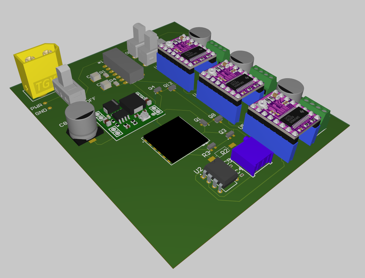
3D rendering of the assembled PCB showing component heights and clearances
Board Specifications:
- Dimensions: 100mm × 50mm
- Layer count: 2
- Power planes: Integrated ground plane
- Mounting: 4x M3 mounting holes
Circuit Schematic
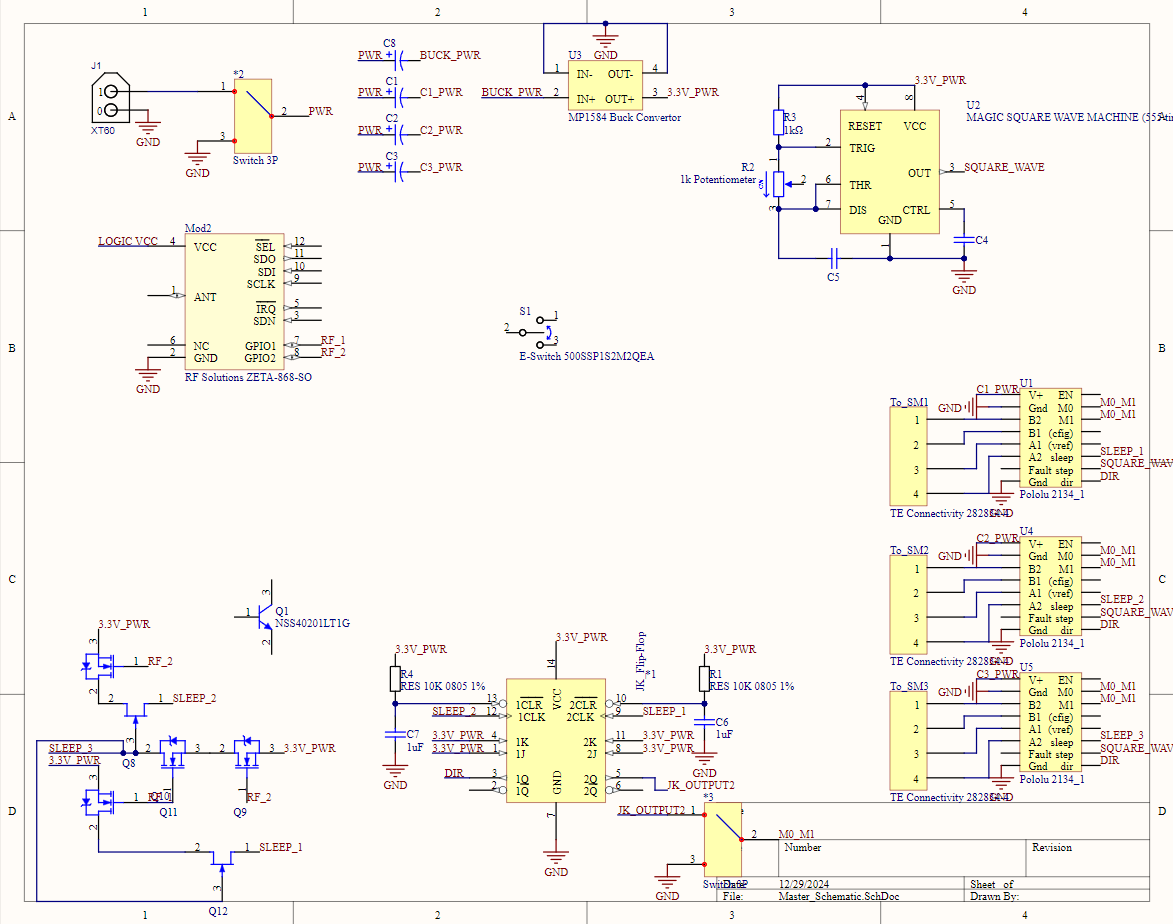
(Semi-)Complete circuit schematic showing electrical connections and component values
Circuit Blocks:
- Power Management: Buck converter with dual power source support
- Motor Control: Three independent stepper driver channels
- Wireless: SPI-based RF communication
- Logic: JK flip-flops and 555 timer for autonomous control
System Architecture

Block diagram showing signal and power flow between components
Signal Flow:
- Wireless commands received by ZETA module
- Command processing through logic circuitry
- Square wave generation for stepping
- Motor control signals distributed to drivers
Technical Specifications:
- Input Power: 7-12V DC or 2S LiPo
- Logic Level: 3.3V
- RF Frequency: 868MHz
- Step Frequency: 0.1-100 Hz (adjustable)
- Control Interface: Sleep, Direction, and Step control per motor
Current Status
PCB design is complete and initial prototypes have been assembled without considering wireless functionality. Testing has verified basic functionality of computer/stepper-motor/kinematic-mount interactions. Next steps include testing wireless capabilities, ordering professionally made PCBs, and furhter integration testing with the mechanical assembly.
Documentation (HTML) formatted with assistance from Anthropic's Claude, an LLM